Updated July 2026 · 8 min read · Serkan İnkaya · Mechanical Engineer, ODTÜ
Why is lighting geometry the real bottleneck in AI inspection?
A defect that does not show up in the image cannot be caught by any model, however good the training. Lighting geometry, the angle and diffusion of the light hitting the part, is what turns a flaw into contrast the sensor can record. Get the geometry wrong and a scratch that a human sees under a shop lamp simply is not there in the captured frame.
Most teams under-invest here. Attention goes to the model, the dataset and the accuracy target, while the light is treated as an afterthought. The reverse is closer to the truth: on many inspection tasks the limiting factor is not the algorithm or the amount of data, it is whether the illumination reveals the feature. Put plainly, lighting, not data, is often the bottleneck. It is telling that the camera side of the problem has a vendor-neutral yardstick, EMVA 1288, the standard for measuring and presenting machine vision sensor and camera specifications, while lighting geometry has no equivalent spec sheet and has to be chosen and proven on your own part.
The good news is that lighting geometry is a solved physics problem with a small number of well-understood options. Three front-lighting geometries cover most surface-inspection work: diffuse, directional (low-angle), and coaxial. Each makes a different class of defect visible, and the right choice follows from the surface finish and the flaw you are hunting. Adente Vision is an edge-AI visual inspection unit built by ADENTE Advanced Engineering Technologies, part of the Aden Group, sold through automation system integrators. Its lighting colour and angle are configurable so one unit can be set to whichever geometry the part needs.
When should you use diffuse lighting?
Diffuse lighting spreads illumination across a wide range of angles so the part is lit evenly with soft, low-contrast light. It is the geometry for matte and curved surfaces, and for any part where you want to suppress glare and read the true colour or texture rather than the shape of the reflection.
Curved and shiny parts are the classic case. Point a hard directional light at a rounded metal or plastic body and you get bright hotspots and dark shadows that swamp the actual defect. A diffuse dome or flat diffuser floods the surface so the reflection is uniform, and a stain, discolouration or texture change stands out against that even field. Diffuse light is also the safe default when the part presentation is not perfectly repeatable.
The trade-off is that diffuse light hides fine three-dimensional relief. A shallow scratch or a light emboss produces very little contrast under flat, even illumination, because there is no grazing angle to cast a shadow into the defect. When the flaw is topographic rather than tonal, you reach for a different geometry.
When does directional or low-angle lighting win?
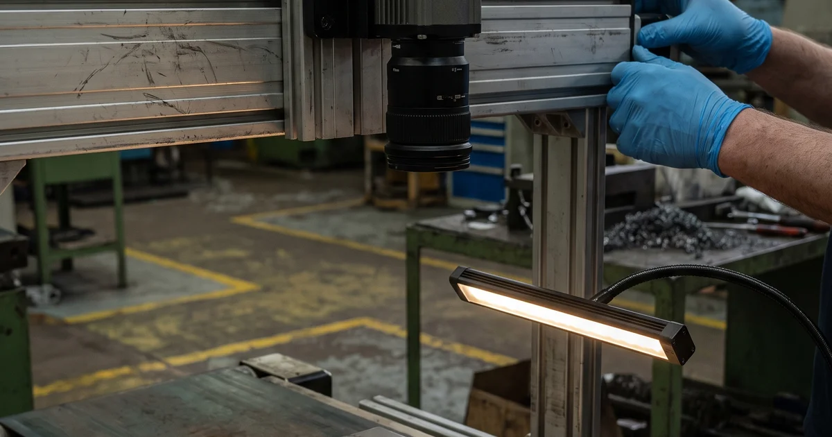
Directional lighting, especially low-angle or grazing light, strikes the surface at a shallow angle so that any raised or recessed feature casts a shadow. It is the geometry for scratches, dents, embossing, engraved marks and edge chips, the topographic defects that a flat light renders invisible.
The mechanism is shadowing. Light coming in almost parallel to the surface skims across it, and wherever the surface steps up or down, the feature blocks the light on one side and brightens on the other. A hairline scratch that is invisible under diffuse light becomes a bright-and-dark line under a low-angle bar. This is why directional light is the workhorse for cosmetic surface inspection and for reading raised or stamped characters.
The cost of directional light is sensitivity to orientation. A scratch running parallel to the light casts almost no shadow, so the geometry has a preferred axis, and textured surfaces can generate shadow noise that competes with the real defect. On a real cell this is tuned by choosing the light angle and colour on the unit rather than by swapping hardware.
What is coaxial lighting best for?
Coaxial lighting sends light along the same axis as the camera, usually through a beam splitter, so the part is lit straight-on from the lens point of view. It is the geometry for flat specular surfaces, mirrors, polished metal, glass, wafers and printed labels on glossy stock, where an angled light would reflect straight out of the field of view and leave the part dark.
On a flat, mirror-like surface, coaxial light returns evenly to the sensor and any deviation from flat, a dent, a coating flaw, a fingerprint, a missing print, shows up as a dark or distorted patch against a bright, uniform background. It is the cleanest way to inspect specular parts for planar defects and for the presence and legibility of print on shiny material, because it removes the hotspot problem that angled light creates on reflective surfaces.
Coaxial light is specialised: it needs a reasonably flat, reflective target and is less useful on matte or three-dimensional parts. That is why a single fixed light rarely suits a mixed inspection portfolio, and why a unit whose colour and angle are configurable is worth more than one tied to a single lighting recipe.
Which lighting geometry for which defect?
Front-lighting geometry maps onto the class of defect you are trying to reveal. The table below is a working summary; treat it as a starting point to test on your own part, not a guarantee, since the result depends on surface finish, colour and presentation.
| Lighting geometry | How it lights the part | Defects it reveals best |
|---|---|---|
| Diffuse | Even, soft light from many angles, glare suppressed | Stains, discolouration, texture change on matte or curved surfaces |
| Directional / low-angle | Grazing light that casts shadows into relief | Scratches, dents, embossing, engraved marks, edge chips |
| Coaxial | On-axis light through a beam splitter, straight-on | Planar defects and print legibility on flat specular surfaces |
| Backlight (industry technique) | Light behind the part, silhouette to the camera | Outline, presence, holes and dimensional edges (context, not the unit's front-light range) |
The first three rows are the configurable front-lighting geometries the unit is built around. Backlighting is a common fourth industry technique, listed for completeness; it sits outside the unit's configurable colour-and-angle front-lighting range.
How do you set the light without a laptop?
On-device preview lets an installer see the live image on the unit while adjusting the light, so lighting is tuned by eye at the cell instead of round-tripping to a laptop. Lighting is the step that most rewards live feedback, because you are looking for the angle and colour that make the defect pop.
This matters during the Aim step of installation. The unit ships with configurable colour and angle on a 24V lighting stage, and the integrator points the camera, adjusts the light, and confirms on the preview that the target defect is visible before training begins. Because the model learns from images, the quality of those images is set here, at the light, so the lighting decision comes before the dataset. For the method that turns those well-lit images into a working model from about 20 good parts, see the sibling post on few-shot anomaly inspection.
This post is a spoke of the pillar guide on AI visual inspection; to see how the unit carries lighting, optics and edge compute in one enclosure, browse the system overview.